
 search
I/N:
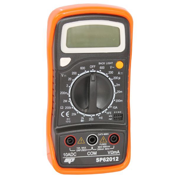
SP62012
DIGITAL MULTIMETER - ELECTRICAL
$45
access_time
Hurry!
10 left in stock
10 left in stock
PAY OPTIONS

Electrical Digital Multimeter
- Back Light
- Data Hold
- Continuing Buzzer
- AC/DC Voltage
- DC Current
- Diode Test
- Temperature Continuity
- Transistor Test
What is electrical digital multimeter?
An electrical digital multimeter is a versatile tool used to measure various electrical parameters, such as voltage, current, and resistance, in both AC and DC circuits. It is widely used by electricians, technicians, and DIY enthusiasts to diagnose and troubleshoot electrical issues in appliances, wiring, and circuits. With its digital display, the electrical digital multimeter provides precise readings, making it easier to identify problems and perform accurate repairs. Many models also feature additional functions like diode testing, continuity checks, and capacitance measurements, making it an essential tool for any electrical work, from simple home tasks to complex industrial repairs.
Where to buy electrical digital multimeter?
You can purchase an electrical digital multimeter from trusted Australian retailers, such as Norva Tools, Total Tools, etc, which offer a wide range of options for professionals and DIY users. Online retailers, like Norva Tools, also provide convenient access to various brands and models of electrical digital multimeters. These retailers stock high-quality tools, ensuring you find the right multimeter to suit your specific electrical diagnostic and testing needs.
Brand
SPTools
User Manual HTML

USER MANUAL
SP62012
DIGITAL
MULTIMETER
ELECTRICAL
RETAIN THESE INSTRUCTIONS
AND ATTACH RECEIPT TO
MANUAL FOR FUTURE
REFERENCE
NOTE: Proof of purchase must be retained by
the customer as it will be required in the
event of a claim under warranty.
AFTER SALES SUPPORT:
WWW.SPTOOLS.COM
AUSTRALIA: Visit the website’s contact page to get in touch with your local service department.
INTERNATIONAL: Use the county selector to get in touch with your service department in your country or region.
 IMPORTANT
ALL PERSONS WHO ARE TO USE THIS EQUIPMENT MUST THOROUGHLY READ AND UNDERSTAND THIS INSTRUCTION MANUAL PRIOR TO OPERATION.

CONTENTS |
|
Product Overview |
2 |
Technical Specifications |
3 |
Features |
4 |
Intended Use |
5 |
Safety Information. |
6 |
Safety Symbols. |
6 |
Operating instructions |
7 |
DC Voltage. |
7 |
DC Current. |
7 |
AC Voltage |
8 |
Diode and Continuity |
8 |
Resistance |
9 |
Transistor hFE Test |
9 |
DC Voltage Measurement |
9 |
DC Current Measurement |
10 |
AC Voltage Measurement |
10 |
Resistance Measurement |
10 |
Diode Test |
10 |
Transistor Test |
11 |
Audible Continuity Test |
11 |
Battery & Fuse Replacement |
11 |
Cleaning and Maintenance |
12 |
Disposal and recycling Instructions |
12 |
After Sales Support |
12 |
Warranty Details |
13 |
|
|
INTRODUCTUCTION |
|
Product Overview
The meter is a handheld 31/2 digital Multimeter for measuring DC and AC voltage, DC current, Resistance, Diode, Transistor and Continuity Test with battery operated systems.
Scope of Delivery
•1 x SP62012 Multimeter, 1 x Black Test Lead, 1 x Red Test Lead & 1 x 9V Battery
2

Technical Specifications
Maximum voltage between |
CAT II 600v |
terminals and earth ground |
|
|
|
Fuse protection |
F 200mA/250V |
|
|
Power supply |
9V battery |
|
|
Display |
LCD, 1999 counts, updates |
|
|
Measuring method |
|
|
|
Over range indication |
Only figure “1” on the display |
|
|
Polarity indication |
|
|
|
Operating environment |
0°c to 50°c |
|
|
Storage environment |
|
|
|
Low battery indicator |
‘’ ‘’ appears on display |
|
|
Size |
138mm x 69mm x 31mm |
|
|
Weight |
Approx. 170g |
|
|
3

Features
1.Display
3 ½ digit, 7 segments, 15mm high LCD
2.Back Light (option)
When this button is pushed, the Back Light of the display is on. After about 5 seconds, the Back Light has an auto off function. Just push the button once to turn on again.
3.Rotary Switch
This switch is used to select functions and desired ranges as well as turn the meter on/off.
4.Hold Button
When this button is pushed, the display will keep the last reading and “ “ symbol will appear on the LCD until pushing it again.
5. “10A” Jack
Plug in connector for RED test lead for 10A measurement
6. “COM” Jack
Plug in connector for BLACK (negative) test lead. 


7. “VΩmA” Jack
Plug in connector for RED (positive) test lead for voltage, resistance and current (except 10A) measurements.
4
Intended Use
•Never exceed the protection limit values indicated in the specifications for each range of measurement.
•When the meter is linked to a measurement circuit, do not touch unused terminals.
•Never use the meter to measure voltages that might exceed 600v above earth ground in category II installations.
•When the value scale to be measured in unknown beforehand, set the range selector at the highest position.
•Before rotating the range selector to change functions, disconnect test leads form the circuit under test.
•When carrying out measurements on TV’s or switching power circuits always remember that there may be high amplitude voltages pulses at test points, which can damage the meter.
•Always be careful when working with voltages above 60V dc or 30Vac rms. Keep fingers be hide the probe barriers while measuring.
•Before attempting to insert transistors for testing, always be sure that test leads have been disconnected from any measurement circuits. Components should not be connected to the hFE socket when making voltage measurements with test leads.
•Never perform resistance measurements on a live circuit.
5

Safety Information
This multimeter has been designed according to
Follow all safety and operating instructions to ensure that the meter is used safely and is kept in a good condition.
Full compliance with safety standards can be guaranteed only with test leads supplied. If necessary, they must be replaced with the type specified in this manual.
Safety Symbols
Important safety information, refer to the operating manual.
Dangerous voltage may be present
Earth ground
Double insulation (Protection class II)
Fuse must be replaced with rating specified.
6

7
200mA
20mA
Range
200∝A
2mA
Resolution Accuracy
0.1∝A±1% of rdg ± 2 digits
1∝A±1% of rdg ± 2 digits
10∝A±1% of rdg ± 2 digits
100∝A±1.5% of rdg ± 2 digits
10A10mA±3% of rdg ± 2 digits Overload Protection: F200mA/250Vfuse. (10A range unfused)
OPERATING INSTRUCTIONS DC Voltage
Range Resolution Accuracy
200mV 100∝V±0.5% of rdg ± 2 digits
2V1mV±0.5% of rdg ± 2 digits
20V 10mV±0.5% of rdg ± 2 digits
200V 100mV ±0.5% of rdg ± 2 digits
600V 1V±0.8% of rdg ± 2 digits
Overload Protection: 250V rms. For 200mV range and 600V dc or rms. Ac for other ranges
DC Current

AC Voltage
Range |
Resolution |
Accuracy |
|
|
|
200V |
100mV |
±1.2 % of rdg ± 10 digits |
|
|
|
600V |
1V |
±1.2 % of rdg ± 10 digits |
Overload Protection: 600V dc or rms. Ac for all ranges. Frequency range: 40Hz
to 400Hz. Response: Average responding, calibrated in rms of a sine wave
Diode & Continuity
Range |
Description |
|
|
|
If continuity exists (about less than 1.5kΩ), |
|
will sound. |
|
|
Show the approx. forward voltage drop of the diode.
Overload Protection: 250Vdc or rms.ac.
8

Resistance
Range |
Resolution |
Accuracy |
|
|
|
200Ω |
0.1Ω |
±0.8% of rdg ± 3 digits |
|
|
|
2kΩ |
1Ω |
±0.8% of rdg ± 2 digits |
|
|
|
20kΩ |
10Ω |
±0.8% of rdg ± 2 digits |
|
|
|
200kΩ |
100Ω |
±0.8% of rdg ± 2 digits |
|
|
|
2MΩ |
1kΩ |
±1.0% of rdg ± 2 digits |
Maximum Open Circuit Voltage: 3.2V
Overload Protection: 250V dc or rms. Ac for all ranges.
Transistor hFE Test
Range |
Test Range |
Test Current |
Test Voltage |
|
|
|
|
NPN & PNP |
Ib=10∝A |
Vce=3V |
|
|
|
|
|
DC Voltage Measurement
1.Connect the red test lead to the VΩmA jack and black test lead to the COM jack.
2.Set the rotary switch at desired DCV position. If the voltage to be measured is not known beforehand, set the range switch at the highest range position and then reduce it until satisfactory resolution is obtained.
3.Connect test leads across the source or load being measured.
4.Read the voltage value on the LCD display along with the polarity of the red lead connection
9

DC Current Measurement
1.For measurements between 200mA and 10A, put the red test lead in the 10A jack
2.Set the rotary switch at the desired DCA position.
3.Open the circuit in which the current is to be measured, and connect the test leads in series with the circuit.
4.Read the current value on the LCD display along with the polarity of red lead connection.
Ac Voltage Measurement
1.Connect the red test lead to the VΩmA jack, and the black test lead to the COM jack.
2.Set the rotary switch to the desired AVC position.
3.Connect the test leads across the source or load being measured.
4.Read the voltage value on the LCD screen.
Resistance Measurement
1.Connect the red test lead to the VΩmA jack and the black test lead to the COM jack. (The polarity of the red lead is positive ‘’+’’.)
2.Set the rotary switch to the desired Ω range position.
3.Connect the test leads across the resistor to be measured and read the LCD display.
4.If the resistance being measured is connected to a circuit, turn off power and disconnect all capacitors before applying test probes.
Diode Test
1.Connect the red test lead to the VΩmA jack and the black test lead to the COM jack. (The polarity of the red lead is positive ‘’+’’.)
2.Set the rotary switch to the ‘’ 
 ’’ position.
3.Connect the red test lead to the anode of the diode to be tested and the black test lead to the cathode of the diode.
4.The approx. forward voltage drop of the diode will be displayed. If the connection is reversed, only figure ‘’1’’ will be shown.
10
Transistor Test
1.Set the rotary switch to the ‘’hFE’’ position.
2.Determine whether the transistor under testing is NPN or PNP and locate the emitter, base and collector leads. Insert then leads into the proper holes of the hFE socket on the front of the panel.
3.Read the approximate hFE value at the test condition of base current 10µA and Vce 3V.
*Attention*
To avoid electrical shock, remove the test leads from measurement circuits before testing a transistor.
Audible Continuity Test
1.Connect the red test lead to the VΩmA jack and the black test lead to the COM jack.
2.Set the range switch to the ‘’ 


 ’’ position.
3.Connect the test leads to two points of the circuit to be tested. If continuity exists, the
Battery & Fuse Replacement
If the battery symbol ‘  ’ appears on the display, it indicates that the battery should be replaced.
The fuse rarely needs replacement. A blown fuse is almost always operator error.
To replace battery and fuse, remove the two screws on the back of the case. Simply remove the old one and replace with a new one.
Be careful to observe battery polarity.
*Warning*
Before attempting to open the case, always be sure that the test leads have been disconnected from measurement circuits. Close the case and tighten screws completely before using the meter to avoid electric shock.
11

Cleaning & Maintenance
•Before opening the case, always disconnect test leads from all energized circuits
•For protection against fire, replace fuse only with the specified voltage and current ratings (F 200mA/250V quick acting)
•Never use the meter unless the back cover is in place and fastened completely.
•Do not use abrasives or solvents on the meter. To clean, use a damp cloth and mild detergent only.
Disposal & Recycling Information
When the tool reaches its end of life, take it to a collection point designated by local authorities for
The separate collection and recycling of your product at the time of disposal will help conserve natural resources and ensure that it is recycled in a manner that protects human health and the environment.
AFTER SALES SUPPORT |
service@austechindustries.com.au |
 1300730056
12

LIMITED WARRANTY
This Limited Warranty applies only to new products* distributed by SP Tools Pty Ltd (“SP Tools”). It is a condition of this Limited Warranty Policy that the purchaser read the owner’s manual for the product and only use the product to the extent or for the purposes stated therein. The purchaser must also ensure that all servicing requirements are completed as listed in the owner’s manual (said servicing is at the owner’s expense). We recommend that all servicing is completed by an authorised service agent and that records of said servicing are retained by the purchaser as proof in the event of a warranty claim.
Whilst the owner’s manual, packaging, and/or other documentation supplied with SP Tools’ products may provide details in respect of a Limited Warranty, the terms set out herein supersede these matters, and this Limited Warranty applies in their place. This warranty is no less advantageous than otherwise described in such other documentation.
SP Tools agrees, subject to the terms and conditions specified below, to repair or replace at SP Tools’ cost, the product purchased by you when the product does not perform in accordance with its specifications during the limited warranty period, due to any fault in manufacturing, materials and/or workmanship. SP Tools is not liable to repair or replace products that the purchaser uses in a manner that is inconsistent with the owner’s manual or in the circumstances set out in paragraphs 1.1 – 1.7 below.
The benefits to the purchaser under this warranty are in addition to other rights and remedies under the Competition and Consumer Act 2010 (Cth). The limited warranty period, within which a defect in the product must appear, commences from the date of purchase and ceases on expiration of the specified term below.
THE LIMITED WARRANTY PERIOD
• SP Speciality Tools – 12 Months
THE PURCHASERS ATTENTION IS DRAWN TO THE FOLLOWING
To the extent permitted by law and subject to this Limited Warranty, and as part of the terms of the sale of the equipment or part thereof: SP Tools shall not be liable for any form of loss, damage, cost, injury or harm of any kind (whether direct, indirect, special or consequential) howsoever arising from the use or supply of the equipment to the purchaser.
EXCLUSIONS TO LIMITED WARRANTY POILICY
This Limited Warranty will not apply where the equipment or any part thereof:
1.1Fails due to an accident (including liquid spillage), abuse, misuse, neglect or normal wear and tear;
1.2Has been used in a manner other than for which it was originally designed;
1.3Has been tampered with or is otherwise than as supplied by SP Tools;
1.4Where any damage, malfunction or other failure of the equipment or any part thereof resulted directly or indirectly from unauthorized persons, adjusting or failing to adjust any part requiring normal maintenance and service (examples include adjustment of tappets, air filter maintenance, lubrication and tightening of screws nuts and bolts);
1.5Malfunctions due to the use of defective or incompatible accessories;
1.6Is damaged by lightning or thunderstorm activity; or
1.7Has been transported to a country where no authorised Service Agents exist.
CLAIMING WARRANTY
This Limited Warranty may be claimed on in the following manner:
2.1In order to make a claim under this Limited Warranty, the purchaser must deliver the equipment or any part thereof to an SP Tools authorised repair agent and pay all costs of transportation and all costs incidental to making a claim under
this Limited Warranty. The purchaser must first contact SP Tools (contact details described above) and request the delivery address of an SP Tools authorised repair agent.
2.2The purchaser must deliver to the repair agent written reasons why the purchaser considers that the purchaser has a claim under this Limited Warranty and must provide all necessary details, including:
•The place, date and from whom the unit or part was purchased.
•The unit or part involved, Model and Serial Number.
•The defect, malfunction or failure in respect of which the claim is being made.
•Proof of service of the unit or part (if applicable)
•Proof of purchase in respect of the unit or part.
2.3If the Limited Warranty claim is valid, the repair agent will carry out repairs and return the product at no charge to the purchaser. These repairs are limited to the Limited Warranty fault identified and as such will not include any other faults due to misuse, abuse, failure to maintain, fair wear and tear or the replacement of serviceable items such as oil, spark plugs, air filters, fuel etc.
Our goods come with guarantees that cannot be excluded under Consumer Law. You are entitled to a replacement or refund for a major failure and for compensation for any other reasonably foreseeable loss or damage. You are also entitled to have the goods repaired or replaced if the goods fail to be of acceptable quality and the failure does not amount to a major failure.
Note: Units which are failing to perform in accordance with specifications due to
13
Write Your Own Review
NEED ANSWERS
Pickup In Store
Norva Tools is one of Melbourne's renowned trade tools stores, and no matter what your tools requirements are, we have you covered. If you don't want to pay for delivery or need your items ASAP, you can pick it up from our tools warehouse in Dandenong, Melbourne. Just bear in mind not all items are in stock. You'll be able to see if they do during the checkout process.
Estimated Delivery Timeframes
If you opted to collect your items, you will receive an email to inform you when your goods are ready for collection.
If you opted for delivery, you will receive an email when the goods have been despatched to the couriers with details so you can track our order.
We aim to despatch all orders within 1-2 business days. In the unusual event of a delay to the dispatch of your order, you will be contacted at the earliest opportunity. Once the order has been despatched the estimated delivery time is as follows:
- Metro (Excludes Hobart Metro) 1-2 business days
- Hobart Metro 3-4 business days
- Regional Areas 3-4 business days
- Remote Areas 6-9 business days
Please note that these delivery timeframes are estimates and are not guaranteed.
Returns
Changed your mind? No worries. You just need to get the product back to us within 14 days, unused and in its original packaging and we'll give you a refund (excluding delivery costs). You can read our full returns policy here (special order items are excluded from this returns policy).
The information below is required for social login
Sign In
Create New Account